
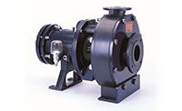
Heavy Duty Industrial Pumps from Hydra-Cell Pumps
Tel (612) 332-5681
Email: sales@wannereng.com
Wanner Engineering, Inc.
1204 Chestnut Avenue, Minneapolis, MN 55403 USA
CALL (612) 332-5681
Hydra-Cell® Principles of Operation
Model
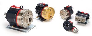
Wobble Plate Models
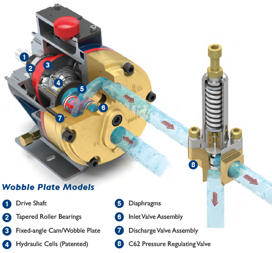
Hydra-Cell wobble plate pumps can have up to five diaphragms, and each diaphragm has its own pumping chamber that contains an inlet and discharge self-aligning horizontal disk check valve assembly (6). As the diaphragms move back, fluid enters the pump through a common inlet and passes through one of the inlet check valves. On the forward stroke, the diaphragm forces the fluid out the discharge check valve (7) and through the manifold common outlet. Equally spaced from one another, the diaphragms operate sequentially to provide consistent, low-pulse flow.
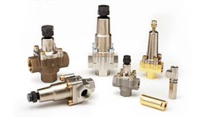
A Hydra-Cell C62 pressure regulating valve (8) is typically installed on the discharge side of the pump to regulate the pressure of downstream process or equipment.
What is a positive displacement pump?
The drive shaft (1) is rigidly held in the pump housing by a large tapered roller bearing (2) at the rear of the shaft and a smaller bearing at the front of the shaft. Set between another pair of large bearings is a fixed-angle cam or wobble plate (3).
As the drive shaft turns, the wobble plate nutates, oscillating forward and back (converting axial motion into linear motion). The complete pumping mechanism is submerged in a lubricating oil bath.
The hydraulic cell (4) is moved sequentially by the wobble plate and filled with oil on its rearward stroke. A ball check valve in the bottom of the piston ensures that the cell remains full of oil on its forward stroke.
The oil held in the Hydra-Cell balances the back side of the diaphragms (5) and causes the diaphragms to flex forward and back as the wobble plate moves. This provides the pumping action.
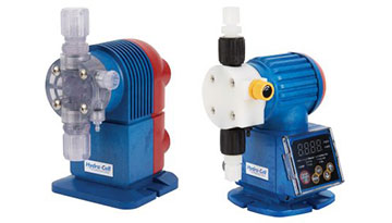
To provide long trouble-free diaphragm life, Hydra-Cell hydraulically balances the diaphragm over the complete pressure range of the pump. The diaphragm faces only a 3 psi (0.21 bar) pressure differential regardless of the pressure at which fluid is being delivered - up to 2500 psi (172 bar) on standard Hydra-Cell models and Hydra-Cell metering pumps.
Model
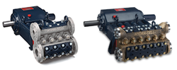
Crank-shaft Models
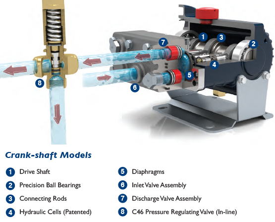
The drive shaft (1) is supported in position by two precision ball bearings (2) positioned at either end of the shaft. Located between these bearings are either one or three cam shaft lobes with connecting rods (3) that are hardened, precision ground, and polished. Maintaining a high level of quality on the cam lobes and connecting rod surfaces ensures proper lubrication and reduced operating temperatures in the hydraulic end of the pump.
As the drive shaft turns, each cam actuates the attached connecting rod that is pinned into position at the end of each hydraulic piston. This action moves the piston forward and backward, converting the axial motion into linear pumping motion. The complete pumping mechanism is submerged in a lubricating oil bath.
Each piston contains a patented hydraulic cell (4) that is moved sequentially by the crank-shaft. The innovative and proprietary Hydra-Cell maintains the precise balance of oil behind the diaphragm (5) regardless of the operating conditions of the pump. The oil in Hydra-Cell is pressurized on the forward stroke of the piston causing the diaphragm to flex, which drives the pumping action. The oil held in the Hydra-Cell balances the diaphragm against the fluid being pumped, maintaining no more than a 3 psi (0.21 bar) differential regardless of the pressure at which the fluid is being delivered - up to 2500 psi (172 bar) on standard Hydra-Cell models and Hydra-Cell metering pumps.
Hydra-Cell crank-shaft pumps can have up to three diaphragms, and each diaphragm has its own pumping chamber that contains an inlet and discharge self-aligning horizontal disk check valve assembly (6). As the diaphragms move back, fluid enters the pump through a common inlet and passes through one of the inlet check valves. On the forward stroke, the diaphragm forces the fluid out of the discharge check valve (7) and through the manifold common outlet. Equally spaced from one another, the diaphragms operate sequentially to provide consistent, low-pulse flow.
A Hydra-Cell C46 pressure regulating valve (8) is typically installed on the discharge side of the pump to regulate the pressure of downstream process or equipment.
Kel-Cell®
Hydra-Cell® Patented Kel-Cell® Diaphragm Protection
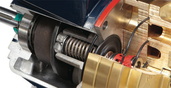
Available on many Hydra-Cell models that use the fixed-angle cam/wobble plate operating principle, Kel-Cell DPC protects Hydra-Cell pumps by safeguarding the diaphragms against abnormal or adverse conditions such as:
- Partially or completely blocked inlet pipe or inlet filter
- Partly or completely closed inlet shut-off valve
- Inadequate liquid supply
- Excessively viscous fluids
- Inadequate discharge pressure
- Other conditions that result in excessive vacuum formed at the inlet of the pump.
These conditions can result from system problems, poor system design, faulty installation, an unplanned operational incident, or other situations that would cause the diaphragms to operate out of hydraulic balance and ultimately deform and rupture.
The Kel-Cell positioning system enhances Hydra-Cell pump performance. It is designed to stabilize the diaphragms in all such conditions and virtually eliminate the possibility of an incidental diaphragm failure caused by adverse system conditions.